|
 |
•rég£؛2024-05-11 پيش´£؛؛د·ت¾Whfw.cc ×÷صك£؛hfw.cc خززھ¼mهe
Assignment (INFO1110)
Introduction
The assignment is an individual assessment. It contributes 30% of your final marks.
The due date for the assignment is on 9th May 2024, 11:59 pm (Sydney time).
This is an assignment, and staff are not permitted to give guidance on your code or how to solve a
specific problem. That is the purpose of the assessment that you are required to perform to achieve
the grade.
You may ask clarification questions about the assignment description. This is often necessary to implement
functionality that may need further understanding to complete. If you have a question to ask on Ed, please
search before asking. With a cohort of almost 2000 students, chances are that someone has already asked a
question you have planned to ask.
Do not wait too long before starting. This assignment needs time and sustained effort.
Remember that you should not be posting any assignment code publicly (including Ed), as this would
constitute academic dishonesty.
Submissions
Late submissions are not accepted unless an approved special consideration or special arrangement in the
form of a Simple Extension or Extension of time has been granted. Please inform staff if you have been
granted this.
All submissions must be made via Ed, including any supporting documentation that is produced
during the planning of the program design such as flowcharts, pseudocodes, and UML class
diagrams.
You may submit as many times before the due date, there is 0 penalty for submitting multiple times.
We will use the latest submission received before the due date for marking. Request to grade files
and derive marks from a combination of different submissions will not be accepted.
It is your responsibility to check that your submission is complete and it meets the following rules:
The Python programs must be able to compile and run within the Ed environment provided.
The Python version that is currently being used on Ed is Python 3.11.8.
Only the files given in the scaffold code will be started by the auto-marker. You are free to write
additional python files, but you must implement all functions and classes provided in the
scaffold. Ensure that you have submitted these files with the correct file name as given in the
questions' scaffold:
board_displayer.py
emitter.py
input_parser.py
laser_circuit.py
mirror.py
photon.py
receiver.py
run.py
sorter.py
Your submission must also include a circuit_for_testing.py and test.py file which
will be used for the manual grading process.
All files specified above must include your name, SID, and unikey in the following format (order
matters!). A placeholder has been provided at the top of the file in the docstring. Providing
incorrect details will cause your submission to fail all test cases.
Name: Xxx Yyy
SID: XXXXXXXXX
Unikey: xxxxXXXX
If you attempt to deceive the auto-grader, obfuscate your code, or do not answer the question by hard coding,
0 marks will be awarded for the question.
Marks
Marks are allocated by the automatic test cases passed for each section, as well as manual grading by
your tutor.
Automatic Test Cases (20/30)
Your marks for this component will be based purely on the automatic test cases you pass. There are 3
types of automatic test cases, all contributing to your mark:
Public: The name of these test cases describes what it is testing, and additionally gives you
feedback on what you got wrong e.g. incorrect output, incorrect return values from functions,
etc. Students can easily see what they got right and wrong.
Hidden: The test case is only named Hidden testcase and does not provide detailed
feedback. You will only be able to see if you passed it or not. The idea behind this is to
encourage students to carefully read through the assignment description and ensure its
reflected in their program.
Private: These tests will only be visible after the deadline. You will not know how many private
test cases there are until the assignment is graded and returned.
There are several features for this assignment, with each one having their own marking proportion.
As example, the first feature SET-MY-CIRCUIT weighs 25% of the automatic test cases. This means
passing all public, hidden and private test cases for this feature gets you 5 out of the 20 marks.
Manual Grading (10/30)
Manual grading will assess the style, layout, and comments, correctness of test case implementation
in test.py and your responses in the test_plan.md document. The test.py file will be executed
during the marking process. Style marking is only applied for reasonable attempts, those which have
code beyond the initial scaffold and are passing at least some test cases.
The style guide for this assessment can be found on the official Python website
https://peps.python.org/pep-0008/.
In addition to the official style guide, you can also refer to these resources:
Code style guide - Part 1
Code style guide - Part 2
If there's an issue running the program, the tutor will not be responsible to debug your program, so please
ensure it runs as expected before making it your final submission.
Restrictions
The following must be read, as it says what you can and can't use. A 20% penalty will be levied on all
testcases passed if one or more of the restricted codes are used in your submission.
Keywords
The following is not allowed.
for
in (this includes the use of __contains__() as in simply invokes this method)
global
lambda
nonlocal
Built-in Functions
The following is not allowed.
all()/any()
map()/filter()
min()/max()/sum()
eval()/compile()/exec()
enumerate()
globals()/locals()
Modules
The following is allowed.
sys
typing
unittest
any module you have written, e.g. emitter .
Every other module is not allowed.
Size Restrictions
A submission containing a more than 5000 lines of code, or larger than 500kB will not be accepted.
To check the file sizes of your files, use the bash commands wc -l *.py and du -skc *.py .
Individual files, such as run.py can be checked with wc -l run.py and du -skc run.py
Help and Feedback
You are encouraged to ask questions about the assignment during the Helpdesk and on the Ed
discussion board. However, remember that you should not be posting any assignment code
publicly, as this would constitute academic dishonesty. Also, you should not disclose your code
or talk about your solutions in any of the PASS sessions.
Friendly Reminder
On occasion, typos or other errors may appear in the assignment description. Sometimes the
description could be clearer. Students and tutors often make great suggestions for improving the
description. Therefore, this assignment description may be clarified up to Week 8, Monday 15,
April. No changes will be made. Revised versions will be clearly marked in the Log of Changes slide
and the most recent version will be updated in the assignment description.
Academic Declaration
By submitting this assignment, you declare the following:
I declare that I have read and understood the University of Sydney Student Plagiarism: Coursework Policy
and Procedure, and except where specifically acknowledged, the work contained in this assignment is my
own work and has not been copied from other sources or been previously submitted for award or
assessment. I also did not use any generative AI tools (including ChatGPT) to assist in writing this
assignment.
I understand that failure to comply with the Student Plagiarism: Coursework Policy and Procedure can
lead to severe penalties as outlined under Chapter 8 of the University of Sydney By-Law 1999 (as
amended). These penalties may be imposed in cases where any significant portion of my submitted work
has been copied without proper acknowledgment from other sources, including published works, the
Internet, existing programs, the work of other students, or work previously submitted for other awards or
assessments.
I realize that I may be asked to identify those portions of the work contributed by me and required to
demonstrate my knowledge of the relevant material by answering oral questions or by undertaking
supplementary work, either written or in the laboratory, in order to arrive at the final assessment mark.
I acknowledge that the School of Computer Science, in assessing this assignment, may reproduce it
entirely, may provide a copy to another member of faculty, and/or communicate a copy of this
assignment to a plagiarism checking service or in-house computer program, and that a copy of the
assignment may be maintained by the service or the School of Computer Science for the purpose of future
plagiarism checking.
Any attempts to trick, break or circumstancing the automate marking system may leads to a mark of 0 and will
be reported to academic honesty committee.
Assignment Breakdown
You will be implementing and emulating a (very rough approximation of) a photonic circuit. In a highlevel overview, photonic circuits use lasers to emit photons (particles of light) which perform
computation through their interactions with other photonic components. There are many parts we
are leaving out, however our main goal is to build a simple emulation of the system which will give
you first-hand experience on implementing a coding project from the ground-up, and hopefully be
interesting enough for you to enjoy.
You do not need any understanding of physics for this assignment, and indeed we will be doing it a degree of
discourtesy by violating rules of quantum mechanics and in turn invent some elements whole-cloth (purefabrication).
The assignment is broken down into separate features. These features are:
1. SET-MY-CIRCUIT
2. GET-MY-INPUTS
3. RUN-MY-CIRCUIT
4. ADD-MY-MIRRORS
The features above are marked purely on automatic test cases.
There is then a separate part for testing Testing (Manually Graded) . This is instead manually
marked, in which the marker will mark your tests (both documentation and implementation) and
code style.
Marks
As discussed in Introduction , there is a marking proportion for each feature. These are marked
purely on the automatic test cases. These are the marking proportions below.
This sums up to a total of 20 marks.
The remaining 10 marks go towards the testing component which is manually graded. You can find
the section here Testing (Manually Graded) .
Summary of Features
This assignment will involve implementing each feature one-by-one. Each feature involves
implementing a set number of functions and classes which will be used in our program. Each feature
is separate, meaning adding a new feature does not require any changes to your existing features to
incorporate. In addition, when running the program, the user can specify which features they want
ran in their program, meaning not necessarily every feature needs to be used. As example, we could
create a circuit from inputs with mirrors added into it (Feature 1, 2 and 4), but not want to run it
(Feature 3). This creates a very flexible and modular program that is easy to extend.
1. SET-MY-CIRCUIT
SET-MY-CIRCUIT will focus on implementing the necessities to setup a circuit. A circuit comprises of
a board in which we can place components on it. Components include emitters (lasers that emits
photons) labelled from A to J and receivers (photodetectors that absorb photons) labelled from
R0 to R9 . We do not yet implement the circuitry functionalities.
By the end of this feature, you will be able to setup a circuit and display it to the user. An example is
we could setup a circuit with some fixed values; a board of size 18x6 characters, with two emitters A
and B and two receivers R0 and R1 (receivers are displayed by their number). We should then be
able to display it such as below.
+------------------+
| |
| B |
| A 0 |
| |
| 1 |
| |
+------------------+
2. GET-MY-INPUTS
GET-MY-INPUTS allows the user to specify what circuit they want to setup by providing inputs to the
program. From this, the user can setup a circuit to their own specifications.
Below is an example of how a user will setup their circuit.
We prepended the inputs with a # symbol so you can clearly see what the inputs to the program are.
$ python3 run.py
Creating circuit board...
> #18 6
18x6 board created.
Adding emitter(s)...
> #A 2 2
> #B 8 1
> #END EMITTERS
2 emitter(s) added.
Adding receiver(s)...
> #R0 15 2
> #R1 8 4
> #END RECEIVERS
2 receiver(s) added.
+------------------+
| |
| B |
| A 0 |
| |
| 1 |
| |
+------------------+
It will first ask to get the size of the board. The size is given in the format <width> <height> . The
example above creates a circuit board of size 18x6 .
It will then ask to add emitters on the board. The emitters are given in the format <symbol> <x> <y> .
Users can add up to 10 emitters, where each emitter is uniquely labelled from A to J . The example
above adds emitter A at position (2, 2) , followed by emitter B at position (8, 1) . Once users are
done adding emitters, they enter END EMITTERS to move on with the program.
Similarly, it will then ask to add receivers on the board. Users can add up to 10 receivers, where each
receiver is uniquely labelled from R0 to R9 . The example above adds receiver R0 at position (15,
2) then R1 at position (8, 4) . The user will be asked to keep adding receivers until 10 are added.
Once users are done adding receivers, they enter END RECEIVERS to move on with the program. At
this point, the only part left to do is to display the board.
By the end of this feature, you will have a run program that will be able to setup a circuit based on
the user's inputs and display the board.
3. RUN-MY-CIRCUIT
RUN-MY-CIRCUIT is responsible for running the circuit. The first step is that it reads from a file the
frequency and direction of each photon emitted. Each line of the file is in the format of <symbol>
<frequency> <direction> where <symbol> is the symbol of the emitter which will emit the photon,
<frequency> is the frequency of the photon and <direction> is the direction in which the photon
will travel.
This is called the pulse sequence. An example of a pulse_sequence.in file is shown below which is
located in /home/input/ .
A 100 E
B 256 S
The pulse sequence above defines that A will emit a photon at 100THz (terahertz) east and B will
emit a photon at 256THz south. After loading the pulse sequence into the circuit, the circuit performs
the following steps:
1. Each emitter emits a photon.
2. In each tick (a tick is a nanosecond), each photon moves. If a photon reaches a receiver, the
receiver will absorb the photon.
3. After each tick, we increment our clock (a simple counter) which keeps track of how long our
circuit has run for.
4. Repeat Steps 2-3 until all photons have been absorbed.
Once a receiver absorbs a photon, the receiver becomes activated in which it's charged with the
photon's energy. An activated receiver can continue absorbing more photons.
Let's look at a small example of running a circuit.
+------------------+
| |
| B |
| A 0 |
| |
| 1 |
| |
+------------------+
With the given circuit, we load the pulse sequence defined above into it. Then, we provide some steps
below to show what happens from here.
At 0ns (nanoseconds), the circuit emits photons. A emits a 100THz photon which will move to the
east and B emits a 256THz photon which will move to the south. When emitting the photons, the
photons initially start inside the emitter (hence the diagram looks no different).
+------------------+
| |
| B |
| A 0 |
| |
| 1 |
| |
+------------------+
At 1ns, each photon moves one unit on the board at their given directions.
+------------------+
| |
| B |
| A. . 0 |
| |
| 1 |
| |
+------------------+
Similarly for 2ns, each photon moves one unit on the board. You can see that we draw the path each
photon takes. You can picture it as the board being made of sand, and each time the photon moves, it
leaves a footstep on the ground.
+------------------+
| |
| B |
| A.. . 0 |
| . |
| 1 |
| |
+------------------+
At 3ns, the photon emitted from B has reached R1 , hence has been absorbed by this receiver. R1 is
now activated.
+------------------+
| |
| B |
| A... . 0 |
| . |
| 1 |
| |
+------------------+
At 13ns, R0 is activated as it absorbs the photon emitted from A .
+------------------+
| |
| B |
| A............0 |
| . |
| 1 |
| |
+------------------+
Running the circuit is now completed as all photons have been absorbed.
By the end of this feature, you will have a run program that can optionally run a circuit given that a
-RUN-MY-CIRCUIT flag is included as an argument. If it is not there, it will not run the circuit. Below is
an example run through of the program.
We prepended the inputs with a # symbol so you can clearly see what the inputs to the program are.
$ python3 run.py -RUN-MY-CIRCUIT
Creating circuit board...
> #18 6
18x6 board created.
Adding emitter(s)...
> #A 2 2
> #B 8 1
> #END EMITTERS
2 emitter(s) added.
Adding receiver(s)...
> #R0 15 2
> #R1 8 4
> #END RECEIVERS
2 receiver(s) added.
+------------------+
| |
| B |
| A 0 |
| |
| 1 |
| |
+------------------+
<RUN-MY-CIRCUIT FLAG DETECTED!>
Setting pulse sequence...
-- (A, B)
Line 1: #A 100 E
-- (B)
Line 2: #B 256 S
Pulse sequence set.
========================
RUNNING CIRCUIT...
========================
0ns: Emitting photons.
A: 100THz, East
B: 256THz, South
5ns: 1/2 receiver(s) activated.
+------------------+
| |
| B |
| A...... 0 |
| . |
| 1 |
| |
+------------------+
10ns: 1/2 receiver(s) activated.
+------------------+
| |
| B |
| A.......... 0 |
| . |
| 1 |
| |
+------------------+
13ns: 2/2 receiver(s) activated.
+------------------+
| |
| B |
| A............0 |
| . |
| 1 |
| |
+------------------+
Activation times:
R1: 3ns
R0: 13ns
Total energy absorbed:
R1: 1.06eV (1)
R0: 0.41eV (1)
========================
CIRCUIT FINISHED!
========================
Here are a few notes about the output above:
When setting the pulse sequence, you may have noticed the lines -- (A, B) and -- (B) .
These are showing the remaining emitters to set the pulse sequence for after each input read
from the pulse_sequence.in file.
When running the circuit, the state of the board is printed every 5ns, along with how many
receivers have been activated. We print the circuit one last time when all photons have been
absorbed, which in this case is at 13ns.
The activation times are printed in ascending order. You can see R1 is first which was activated
at time 3ns. Next was R0 which was activated at 13ns.
Next, the total energy absorbed is printed in descending order. The energy absorbed is
displayed in electronvolts (eV) and the number following it is the number of photons absorbed
by the receiver. In this case, R1 stores 1.06eV and absorbed 1 photon. Similarly, R2 stores
0.41eV and absorbed 1 photon
You will find out how to convert THz to electronvolts (eV) in RUN-MY-CIRCUIT . For now, just know that
a higher frequency (THz) means a higher energy (eV).
4. ADD-MY-MIRRORS
ADD-MY-MIRRORS allows the user to add mirrors into the circuit. Mirrors are able to reflect photons
off its surface which changes the direction in which the photons travel. Mirrors are a component just
like emitters and receivers.
Mirrors are given in the format <symbol> <x> <y> , similar to emitters and receivers. There are 4
different types of mirrors which include / , \ , > and ^ . We won't go in the details for each mirror,
just know that it will reflect photons off it depending on both the type of mirror and the direction of
the photon. Below is an example valid input of a mirror.
\ 2 5
This would create a mirror / and place it at position (2, 5) on the circuit board. Since mirrors
aren't uniquely labelled (you can have multiple mirrors with the same symbol), users can enter as
many mirrors as they want, as long as there is space for it. Once they are finished, they can stop
adding mirrors by entering END MIRRORS .
By the end of this feature, you will have a run program that can optionally include mirrors given that
the -ADD-MY-MIRRORS flag is included as an argument. If it is not there, it will not involve mirrors in
the program. Below is an example run through of the program.
We prepended the inputs with a # symbol so you can clearly see what the inputs to the program are.
$ python3 run.py -RUN-MY-CIRCUIT -ADD-MY-MIRRORS
Creating circuit board...
> #18 6
18x6 board created.
Adding emitter(s)...
> #A 2 2
> #B 8 1
> #END EMITTERS
2 emitter(s) added.
Adding receiver(s)...
> #R0 15 2
> #R1 8 4
> #END RECEIVERS
2 receiver(s) added.
<ADD-MY-MIRRORS FLAG DETECTED!>
Adding mirror(s)...
> #\ 2 5
> #^ 5 5
> #/ 5 4
> #\ 11 1
> #> 11 4
> #/ 15 4
> #END MIRRORS
6 mirror(s) added.
+------------------+
| |
| B \ |
| A 0 |
| |
| / 1 > / |
| \ ^ |
+------------------+
<RUN-MY-CIRCUIT FLAG DETECTED!>
Setting pulse sequence...
-- (A, B)
Line 1: #A 100 S
-- (B)
Line 2: #B 256 E
Pulse sequence set.
========================
RUNNING CIRCUIT...
========================
0ns: Emitting photons.
A: 100THz, South
B: 256THz, East
5ns: 0/2 receiver(s) activated.
+------------------+
| |
| B..\ |
| A . 0 |
| . . |
| . / 1 > / |
| \..^ |
+------------------+
10ns: 1/2 receiver(s) activated.
+------------------+
| |
| B..\ |
| A . 0 |
| . . |
| . /..1 >.../ |
| \..^ |
+------------------+
12ns: 2/2 receiver(s) activated.
+------------------+
| |
| B..\ |
| A . 0 |
| . . . |
| . /..1 >.../ |
| \..^ |
+------------------+
Activation times:
R1: 10ns
R0: 12ns
Total energy absorbed:
R0: 1.06eV (1)
R1: 0.41eV (1)
========================
CIRCUIT FINISHED!
========================
SET-MY-CIRCUIT (5 marks)
Introduction
A circuit board is defined on a two dimensional plane.
+------------------+
| |
| |
| |
| |
| |
| |
+------------------+
Each circuit can have up to 10 emitters and 10 receivers. Photons are emitted from emitters A to J
which may be received by a receiver R0 to R9 . The receivers on the board are displayed by their
number.
+------------------+
| |
| B |
| A 0 |
| |
| 1 |
| |
+------------------+
We can see that the circuit board has size 18x6 . The size does not include the border around the
board.
These are the positions of the emitters and receivers. The top left corner has position (0, 0) .
A : (2, 2)
B : (8, 1)
R0 : (15, 2)
R1 : (8, 4)
This should be enough information to cover the context of this feature, but you can scout for
additional information in Assignment Breakdown under Section 1. SET-MY-CIRCUIT if needed.
Your Task
The SET-MY-CIRCUIT feature will allow you to setup a circuit board just like the example in the above
section. In an implementation perspective, you'll be able to make a LaserCircuit instance and add
your own Emitter and Receiver instances into it. You will also be able to output the board on the
screen.
In this feature, you will be adding implementation to the following:
Emitter class
Receiver class
BoardDisplayer class
LaserCircuit class
There may be some functionalities in these classes that will be skipped. It will be specified what you need to
implement for this feature.
1. Emitter
An Emitter instance represents a laser which emits a photon with a frequency (THz) and direction
(either right or downwards).
These are the instance attributes of an Emitter instance.
When initialising an Emitter instance, it is given a symbol from A to J which is how this emitter
will be shown on the board. The emitter is given an x and y position which is its position on the
board. At the start, frequency is 0 and direction is None . This is later set by the pulse sequence
once we get up to running the circuit, hence the reason why pulse_sequence_set also starts false.
component_type is a constant with value 'emitter' which acts as an identity string for all emitters.
These are the instance methods of an Emitter instance that you'll need to implement for this
feature.
2. Receiver
A Receiver instance represents a photodetector that charges up by absorbing photons. When a
receiver absorbs a photon, it becomes activated in which it is charged with the photon's energy. An
activated receiver can keep absorbing more photons to store more energy. A receiver stores
information about the number of photons it has absorbed, the total energy it is charged with and
when it was activated. The amount of energy a receiver is charged with directly corresponds to the
frequency of all photons it absorbs summed up.
These are the instance attributes of a Receiver instance.
When initialising a Receiver instance, it is given a symbol from R0 to R9 . The number ( 0 to 9 ) is
what will be used to show the receiver on the board. The receiver is given an x and y position which
is its position on the board. At the start, total_energy is 0.0, photons_absorbed is 0 as it starts with
no photons absorbed. Similarly, activated is false and activation_time is 0 as it must absorb a
photon to become activated. component_type is a constant with value 'receiver' which acts as an
identity string for all receivers.
These are the instance methods of a Receiver instance that you'll need to implement for this
feature.
3. BoardDisplayer
A BoardDisplayer instance is responsible for displaying the circuit board. It's considered a helper
class as it does not assist with the functionality of the circuit. Its only purpose is to store a list of list of
strings (2 dimensional list of strings) representing the board. Each time a component is added to the
circuit, the BoardDisplayer instance is updated to store the component's symbol in its assigned
position in the 2D list.
These are the instance attributes of a BoardDisplayer instance.
When initialising a BoardDisplayer instance, it is given a width and height which will then be
used to initialise an empty board of that size.
These are the instance methods of a BoardDisplayer instance that you'll need to implement for this
feature.
Below we will provide clarifications for some of the instance methods to implement.
3.1 create_board
The create_board method takes in a width and height and will create a list of list of strings
representing an empty board of size width x height . As example, let's say width is 6 and height
is 3. Then the function needs to return the following:
[
[' ', ' ', ' ', ' ', ' ', ' '],
[' ', ' ', ' ', ' ', ' ', ' '],
[' ', ' ', ' ', ' ', ' ', ' ']
]
You can see it's one list containing 3 inner-lists, representing our height. These are the rows.
Each row contains 6 elements, representing the width. These are the columns. Each element is a
single space, representing an empty cell on the board.
In the BoardDisplayer constructor, the board instance attribute should be given the return value of the
create_board method.
3.2 add_component_to_board
The add_component_to_board method takes in a component and adds its symbol on the board at
its assigned position.
It shouldn't scare you that it can accept different types of components. They all have common properties, that
being their symbol , x and y value. Since every component has these attributes, it doesn't actually matter
what component is passed in, you can treat them all the same.
Let's take the empty board we just made, and say we call the add_component_to_board method
twice. In the first call, we passed an emitter with symbol A and position (3, 1) and in the second
call, we passed a receiver with symbol R9 and position (0, 2) . Then, the board attribute will now
look like this.
[
[' ', ' ', ' ', ' ', ' ', ' '],
[' ', ' ', ' ', 'A', ' ', ' '],
['9', ' ', ' ', ' ', ' ', ' ']
]
A is at board[1][3] and R9 is at board[2][0] .
To access position (x, y) on the board, it is board[y][x] as the first index represents the row (height) and
the second index represents the column (width).
3.3 print_board
For print_board , it will translate the board attribute into output. Let's take the example above
where we just put in an emitter and a receiver. After calling the method, it would print the following:
+------+
| |
| A |
|9 |
+------+
You can see the border is not included in the size (it wraps around the board).
4. Laser Circuit
A LaserCircuit instance is responsible for storing all components of the circuit and handling the
computation of running the circuit. It's responsible for delegating tasks to the specific components
e.g. making each emitter emit a photon, getting each photon to move and interact with components,
etc. In general, this class is responsible for handling any task related to the circuit.
These are the instance attributes of a LaserCircuit instance.
When initialising a LaserCircuit instance, it is given a width and height used to create the
board_displayer . The laser circuit initially starts with 0 components, so the list of emitters ,
receivers and mirrors start empty. Similarly, the list of photons start empty as no photons have
been emitted. clock starts at 0, this will increment once we begin running the circuit.
These are the instance methods of a LaserCircuit instance that you'll need to implement for this
feature.
4.1 print_board
The print_board method is straightforward. We simply call the print_board method of
board_displayer . This is so when we have a LaserCircuit instance, we can easily print the board.
4.2 get_collided_emitter
The get_collided_emitter checks if entity has the same x and y value as any emitter in the
circuit and returns that emitter if there exists a collision, else it returns None . Remember that all
components and photons have an x and y value, so we shouldn't need to worry about what specific
entity was passed in to check the collision. This also applies for get_collided_receiver in the
context that we are checking receivers instead of emitters.
Below are more methods that need to be implemented for this feature.
4.3 add_emitter
For add_emitter , here are the error messages for the checks you must perform.
Note from the method description that if at any point an error occurs, you return False . As example, if the
emitter is out-of-bounds, after printing the error message you return False , meaning the remaining 2 checks
are skipped.
Below are more methods that need to be implemented for this feature.
4.4 add_receiver
Similarly, here are the error messages for the checks you must perform. They mostly borrow from
add_emitters .
Below are the remaining methods that need to be implemented for this feature.
Let's run through of an example of initialising a LaserCircuit instance, printing the board, then
adding some components and printing the board again. We show an example of each error message
that can occur when adding a component into the circuit.
The following is run in a Python interactive session.
>>> from emitter import Emitter
>>> from receiver import Receiver
>>> from laser_circuit import LaserCircuit
# create the circuit and print board
>>> circuit = LaserCircuit(18, 6)
>>> circuit.print_board() # should initially be empty board
+------------------+
| |
| |
| |
| |
| |
| |
+------------------+
# create our emitters
>>> e1 = Emitter('A', 2, 2)
>>> e2 = Emitter('B', 8, 1)
# make an extra emitter to show error
>>> e3 = Emitter('C', 8, 1)
# add the emitters and print the board
>>> circuit.add_emitter(e1)
>>> circuit.add_emitter(e2)
>>> circuit.add_emitter(e3)
Error: position (8, 1) is already taken by emitter 'B'
>>> circuit.print_board()
+------------------+
| |
| B |
| A |
| |
| |
| |
+------------------+
# create out receivers
>>> r1 = Receiver('R0', 15, 2)
>>> r2 = Receiver('R1', 8, 4)
# make extra receivers to show error
>>> r3 = Receiver('R1', 9, 0)
>>> r4 = Receiver('R1', 0, 13)
# add the receivers and print the board
>>> circuit.add_receiver(r1)
>>> circuit.add_receiver(r2)
>>> circuit.add_receiver(r3)
Error: symbol 'R1' is already taken
>>> circuit.add_receiver(r4)
Error: position (0, 13) out-of-bounds on 18x6 circuit board
>>> circuit.print_board()
+------------------+
| |
| B |
| A 0 |
| |
| 1 |
| |
+------------------+
GET-MY-INPUTS (5 marks)
Introduction
In SET-MY-CIRCUIT , we implemented some classes to provide the base for building our circuit. Now
we want to allow the user to provide inputs to the program in which they will be able to create a
circuit to their own specifications.
On top of what's covered on Assignment Breakdown under Section 2. GET-MY-INPUTS , we will also
be covering input parsing. By this, we mean when users enter any input, whether it be for the board
size, emitters, or receivers, you will need to parse the input to validate that the input is correct.
An example of input parsing is shown below, where the user enters an incorrect size for the circuit
board multiple times.
Inputs are prepended with a # in the output snippets for your own clarity.
Creating circuit board...
> #18
Error: <width> <height>
> #18 six
Error: height must be an integer
> #18 6
18x6 board created.
Until the user enters a valid size, the program will keep asking for input. You can see entering only the
width displayed an error message Error: <width> <height> . The program then asked for input
again, in which the user incorrectly entered the height, displaying an error message Error: height
must be an integer . On the third input, the user entered a valid size, creating the board where the
program can proceed.
This is just a small look at the input parsing, there will be more to cover.
Your Task
The GET-MY-INPUTS feature will allow the user to set up a circuit to their specifications using inputs.
From an implementation perspective, you'll be making a LaserCircuit instance and adding
Emitter and Receiver instances into it based on the user's inputs. Then, you'll display the circuit
board to the user.
In this feature, you will be adding implementation to the following:
input_parser module
run module
There may be some functionalities in these modules that will be skipped. It will be specified what you need to
implement for this feature.
1. Input Parser
The input_parser module is responsible for parsing the inputs of the program. We define parsing as
checking the validity of what has been entered to determine if it's valid. If it's not valid, an appropriate
error message should be printed to indicate what was wrong with the input. Whenever we retrieve
input in the program, we should be using functions from this module to validate it.
These are the functions in the input_parser module that you'll need to implement for this feature.
1.1 parse_size
For parse_size , here are the error messages for the checks you must perform.
Note from the method description that if at any point an error occurs, you return None . As example, if the first
check passes but the second check fails (where width is not an integer), we return None , meaning the
remaining 3 checks are skipped.
Here are some examples of running parse_size in a Python interactive session.
Output Snippet 1 - Calling parse_size in a Python interactive session.
>>> from input_parser import parse_size
# Error 1
>>> size = parse_size('6')
Error: <width> <height>
>>> size
None
# Error 2
>>> size = parse_size('six 3')
Error: width is not an integer
>>> size
None
# Error 3
# Note: width is not positive (Error 4), however Error 3 is checked first
>>> size = parse_size('-6 three')
Error: height is not an integer
>>> size
None
# Error: 4
# Note: height is not positive (Error 5), however Error 4 is checked first
>>> size = parse_size('-6 -3')
Error: width must be greater than 0
>>> size
None
# Error 5
>>> size = parse_size('6 0')
Error: height must be greater than 0
>>> size
None
# No errors
>>> size = parse_size('6 3')
>>> size
(6, 3)
Below are more methods that need to be implemented for this feature.
1.2 parse_emitter
For parse_emitter , here are the error messages for the checks you must perform.
The checks and error messages are identical for parse_receiver , with the only exception being when
checking the symbol. Instead of A to J , we need to check from R0 to R9 ,. and the error message would be
Error: symbol is not between R0-R9 .
Here are some examples of running parse_emitter in a Python interactive session.
Output Snippet 2 - Calling parse_emitters in a Python interactive session.
>>> from input_parser import parse_emitter
# Error 1
>>> emitter = parse_emitter('A 0')
Error: <symbol> <x> <y>
>>> emitter
None
# Error 2
>>> emitter = parse_emitter('K 0 0')
Error: symbol is not between 'A'-'J'
>>> emitter
None
# Error 3
# Note: y is not an integer (Error 4), however Error 3 is checked first
>>> emitter = parse_emitter('A B C')
Error: x is not an integer
>>> emitter
None
# Error 4
>>> emitter = parse_emitter('A 0 zero')
Error: y is not an integer
>>> emitter
None
# Error 5
>>> emitter = parse_emitter('A -1 0')
Error: x cannot be negative
>>> emitter
None
# Error 6
>>> emitter = parse_emitter('A 0 -3')
Error: y cannot be negative
>>> emitter
None
# No errors
>>> emitter = parse_emitter('A 0 0')
>>> emitter
<Object: Emitter> # an emitter instance, just shown as this for readability
2. run
The run module is responsible for running the entire program. In summary, it needs to take in the
inputs, process them into creating the circuit, and then print the board. A large part of the
implementation will revolve around calling functions and creating instances of classes we have
implemented from previous works.
These are the functions of the run module that you'll need to implement for this feature.
2.1 initialise_circuit
This function is responsible for getting the inputs of the board size, emitters, and receivers and
creating the circuit. These are the general steps for this function.
1. Gets input from the user for the board size to create a circuit.
2. Until the maximum amount of emitters are added (10) or END EMITTERS is inputted by the
user, for each input:
1. Create a new emitter with the specified values.
2. Add the new emitter into the circuit.
3. Until the maximum amount of receivers is added (10), or END RECEIVERS is inputted by the
user, for each input:
1. Create a new Receiver instance with the specified values.
2. Add the new emitter into the circuit.
The steps above don't include the instance when an invalid input is given. If an invalid input is given,
it will simply print an error message stating the cause of the error and ask for input again.
1. Size
Inputs are prepended with a # in the output snippets for your own clarity.
This is an example of entering the board size to create the circuit board.
Creating circuit board...
> #18 6
18x6 board created.
Now let's look at an example with some errors:
Creating circuit board...
> #18 0
Error: height must be greater than zero
> #18
Error: <width> <height>
> #18 6
18x6 board created.
You can see that it will continuously take in input until the user enters a valid size. Notice the above is
what we have just implemented in parse_size , how convenient!
2. Emitters
This is an example of entering the values to add new emitters to the circuit board.
Adding emitter(s)...
> #A 2 2
> #B 8 1
> #END EMITTERS
2 emitter(s) added.
You can see that the user explicitly ended up adding the emitters with END EMITTERS . Without it, it
would keep prompting for input until 10 emitters have been added (even if there are 100 errors, it
will keep prompting until 10 emitters are added).
Here's another example where they add 10 emitters to the circuit board.
Adding emitter(s)...
> #A 0 1
> #B 1 2
> #D 2 1
> #E 3 3
> #C 4 1
> #H 5 5
> #G 6 1
> #F 7 4
> #I 8 1
> #J 9 6
10 emitter(s) added.
Now let's look at an example with some errors:
Adding emitter(s)...
> #A 2 2
> #A 3 4
Error: symbol 'A' is already taken
> #B 2 2
Error: position (2, 2) is already taken by emitter 'A'
> #B 8 1
> #END EMITTERS
2 emitter(s) added.
You can see that the program will continuously take in input until either 10 emitters are added, or
they end it explicitly with END EMITTERS . Notice the above is what we have just implemented in
parse_emitter and add_emitter , how convenient!
3. Receivers
This is an example of entering the values to add new emitters to the circuit board.
Adding receiver(s)...
> #R0 15 2
> #R1 8 4
> #END RECEIVERS
2 receiver(s) added.
You can see it's essentially the same input format as adding emitters.
Adding receiver(s)...
> #R0 15 2
> #R0 8 4
Error: symbol 'R0' is already taken
> #R1 15 2
Error: position (15, 2) is already taken by receiver 'R0'
> #R1 8 4
> #END RECEIVERS
2 receiver(s) added.
4. Putting it Together
This is an example output snippet of what this function does from start to end.
Output Snippet 4 - Calling initialise_circuit in a Python interactive session.
Inputs are prepended with a # in the output snippets for your own clarity.
>>> from run import initialise_circuit
>>> circuit = initialise_circuit()
Creating circuit board...
> #18 6
18x6 board created.
Adding emitter(s)...
> #B 8 1
> #A 2 2
> #END EMITTERS
2 emitter(s) added.
Adding receiver(s)...
> #R1 8 4
> #R0 15 2
> #END RECEIVERS
2 receiver(s) added.
>>> circuit
>>> <Object: LaserCircuit>
The function will return a LaserCircuit instance with the following values:
A width of 18 and height of 6 .
Emitters A with position (2, 2) and B with position (8, 1) in the circuit's emitters .
Receivers R1 with position (8, 4) and R0 with position (15, 2) in the circuit's receivers .
The BoardDisplayer instance should inheritably have a fully up-to-date board to display.
Here is a detailed look at the LaserCircuit returned from the example above (we exclude the self
keyword to avoid clutter).
laser_circuit:
emitters: [<Object: Emitter A>, <Object: Emitter B>]
receivers: [<Object: Receiver R0>, <Object: Receiver R1>]
photons: []
mirrors: []
width: 18
height: 6
board_displayer: <Object: BoardDisplayer>
width: 18
height: 6
board: [
[' ', ' ', ' ', ' ', ' ', ' ', ' ', ' ', ' ', ' ', ' ', ' ', ' ', ' ', ' ', ' ', ' '
[' ', ' ', ' ', ' ', ' ', ' ', ' ', ' ', 'B', ' ', ' ', ' ', ' ', ' ', ' ', ' ', ' '
[' ', ' ', 'A', ' ', ' ', ' ', ' ', ' ', ' ', ' ', ' ', ' ', ' ', ' ', ' ', '0', ' '
[' ', ' ', ' ', ' ', ' ', ' ', ' ', ' ', ' ', ' ', ' ', ' ', ' ', ' ', ' ', ' ', ' '
[' ', ' ', ' ', ' ', ' ', ' ', ' ', ' ', '1', ' ', ' ', ' ', ' ', ' ', ' ', ' ', ' '
[' ', ' ', ' ', ' ', ' ', ' ', ' ', ' ', ' ', ' ', ' ', ' ', ' ', ' ', ' ', ' ', ' '
]
clock: 0
You can see that the emitters and receivers are sorted, regardless of what order it is added in from
the inputs.
2.2 main
The main function takes in one argument args which is the command line arguments of the
program. For now, you can ignore this. This function for now will simply just call
initialise_circuit , get the LaserCircuit instance and use its methods to print the board. It
should be the shortest function in this module!
Output Snippet 6 - Output from calling main function
Inputs are prepended with a # in the output snippets for your own clarity.
>>> from run import main
>>> main([])
Creating circuit board...
> #18 6
18x6 board created.
Adding emitter(s)...
> #A 2 2
> #B 8 1
> #END EMITTERS
2 emitter(s) added.
Adding receiver(s)...
> #R0 15 2
> #R1 8 4
> #END RECEIVERS
2 receiver(s) added.
+------------------+
| |
| B |
| A 0 |
| |
| 1 |
| |
+------------------+
5. Output Examples
When running the run program, it simply should be just calling the main function.
Output Snippet 7 - Output from run program
Inputs are prepended with a # in the output snippets for your own clarity.
$ python3 run.py
Creating circuit board...
> #12 0
Error: height must be greater than zero
> #12 4
12x4 board created.
Adding emitter(s)...
> #END RECEIVERS
Error: <symbol> <x> <y>
> #D 2 2
> #A 4 1
> #J 9 0
> #I 11 2
> #E 7 1
> #B 20 20
Error: position (20, 20) is out-of-bounds of 12x4 circuit board
> #B 0 0
> #C 8 1
> #F 5 2
> #G 1 0
> #H 10 1
10 emitter(s) added.
Adding receiver(s)...
> #R0 9 0
Error: position (9, 0) is already taken by emitter 'J'
> #R0 0 3
> #R1 1 3
> #R2 2 3
> #R3 4 3
> #R4 5 3
> #R5 **
> #R6 8 3
> #R7 9 3
> #R8 10 3
> #R9 11 3
10 receiver(s) added.
+------------+
|BG J |
| A EC H |
| D F I|
|012 34 56789|
+------------+
RUN-MY-CIRCUIT (7 marks)
Introduction
In GET-MY-INPUTS , we have allowed users to set up a circuit based on the their inputs. Now we want
to be able to run the circuit, which comprise of photons travelling across the circuit board and
interacting with components.
Please have a read of the Assignment Breakdown under Section 3. RUN-MY-CIRCUIT as it covers the
basis for this entire feature. There are only some very small parts on top of what's covered on that
page that need to be implemented which will be explained once we get to it.
This feature requires the most implementation out of the rest, so we have broke it down into two
parts for simplicity. Part 1 (15%) focuses on implementing individual functionalities such as moving
photons, displaying photon paths, energy conversions, etc. Part 2 (20%) will then cover putting
everything together so we can run the circuit from start-to-end when running the program.
Your Task
The RUN-MY-CIRCUIT feature will allow the user to run their circuit. They can optionally choose to do
so by adding the -RUN-MY-CIRCUIT flag as an argument. You can view it as an extension of the
existing program.
In Part 1 (Sections **5), you will be adding implementation to the following:
Photon class
Emitter class
Receiver class
BoardDisplayer class
LaserCircuit class
This will cover implementing the individual functionalities for running the circuit.
In Part 2 (Sections 6-8), you will be adding implementation to the following:
LaserCircuit class
input_parser module
run module
This will cover putting everything together so we can run the circuit from start-to-end when running
the program.
Part 1 will cover implementing the logic for the photons and components.
1. Photon
A Photon instance is a particle of light that is emitted by an Emitter instance and travels along the
circuit board. Photons have a frequency (THz) and direction in which they move in. They can interact
with components in the circuit such as a Receiver instance in which it can be absorbed.
These are the instance attributes of a Photon instance.
When initialising a Photon instance, it takes in a x and y position, as well as a frequency and
direction . These values will come from the emitter it is emitted from. Initially, absorbed is false. All
photons have a dot as their symbol.
These are the instance methods of a Photon instance that you'll need to implement for this feature.
1.1 move
When a photon moves, it moves one unit depending on its direction.
direction : 'N' , y is decremented (moving up).
direction : 'E' , x is incremented (moving right).
direction : 'S' , y is incremented (moving down).
direction : 'W' , x is decremented (moving left).
Here are some examples of running move in a Python interactive session.
Output Snippet 1 - Calling instance method move in Python interactive session.
>>> from photon import Photon
>>> photon = Photon(0, 0, 100, 'S')
# initial position
>>> photon.x, photon.y
(0, 0)
# move up
# 2, 2 is the board with and height respectively
>>> photon.move(2, 2)
>>> photon.x, photon.y
(0, 1)
# move right
>>> photon.set_direction('E')
>>> photon.move(2, 2)
>>> photon.x, photon.y
(1, 1)
# going out of bounds
>>> photon.move(2, 2)
>>> photon.x, photon.y
(1, 1)
# notice the position is still (1, 1), we do not allow it to move out of the circuit
# now the photon is absorbed
>>> photon.absorbed
True
1.2 interact_with_component
You may find it easier to implement this method once you have at least read the implementation for
Receiver in section 3.
Below are the remaining methods that need to be implemented for this feature.
2. Emitter
You will be finishing the implementation of the Emitter instance. These methods relate to the
running of the circuit.
Below we will provide clarifications for some of the instance methods to implement.
2.1 emit_photon
For further clarification on emit_photon() , this method needs to create and return a Photon
instance. This photon should inherit the position, frequency, and direction of the emitter.
Output Snippet 2 - Calling instance method emit_photon of Emitter instance in Python interactive
session.
>>> from emitter import Emitter
>>> emitter = Emitter('A', 0, 0)
>>> emitter.set_pulse_sequence(100, 'N')
# get the photon emitted from the emitter
>>> photon = emitter.emit_photon()
>>> photon.x, photon.y
(0, 0)
>>> photon.frequency
100
>>> photon.direction
'N'
2.2 __str__
For the __str__ method, printing the emitter instance itself should output the custom format string.
As an example, if we had an emitter A that has frequency set to 100 and the direction set to 'N' ,
this would be the output.
Output Snippet 3 - Printing an Emitter instance in Python interactive session.
>>> from emitter import Emitter
>>> emitter = Emitter('A', 0, 0)
>>> emitter.set_pulse_sequence(100, 'N')
>>> emitter.frequency
100
>>> emitter.direction
'N'
>>> print(emitter)
A: 100THz, North
3. Receiver
You will be finishing the implementation of the Receiver instance. These functions and methods
relate to the running of the circuit.
Below we will provide clarifications for some of the instance methods to implement.
3.1 convert_frequency_to_energy
We promised we would not involve any physics in this assignment, so we have implemented this function for
you. However, it cannot hurt to get some context behind its workings. 😄
To calculate how much energy a photon carries, we use a constant that relates a photon's frequency
to its energy in joules known as the Planck Constant h.
h = 6.62607015 × 10 J ⋅ −34 Hz−1
The unit represents joules per hertz. Frequency (Hz) is defined as a cycle per second, hence
can be substituted as or more intuitively .
J ⋅ Hz−1 Hz−1
s−1 1/s
The Planck Constant is a very significant physical constant in quantum mechanics as it describes the
behaviour of particles on the atomic scale. In summary, it defines the quantum nature of energy and
relates the energy of a photon to its frequency. It is this theory that electromagnetic energy cannot
flow continuously, and must transfer energy through discrete values, allowing us to mathematically
compute how the universe operates on an atomic scale such as stellar evolution (the lifetime of a
star).
Let's say that we have a photon with 256THz. To calculate its energy we have the given equation
, where given Planck's constant and the frequency of the photon in hertz (Hz), we can
calculate its energy in joules (J). Since 1THz is equal to Hz, we simply just need to multiply it
by a factor of 12 to get our units correct, giving us the following equation.
E = h × f h f
E 1012
E = h × 256 × 1012
The final part is that is in joules. We want it to be in electronvolts (eV). By definition, one
electronvolt is the energy acquired by an electron when it is accelerated through a potential difference
of 1 volt. We have it that 1eV is equal to . So we simply need to divide by
this amount.
E
1.60217662 × 10 J −19 E
eV = 1.60217662 × 10⁻¹⁹J
E
Hence, let us say we want to convert 256THz to electronvolts. The equation is given as follows.
eV = = 1.60217662 × 10⁻¹⁹J
6.62607015 × 10 × 256 × 10 J ⋅ Hz −34 12 −1
1.06 2 ( ) dp
Knowing any of the above is likely not helpful for the assignment, but you will need to use this
function to convert frequencies to energy.
3.2 absorb_photon
The absorb_photon is responsible for handling the logic for the receiver absorbing a photon. You will
need to mathematically convert the photon's frequency (THz) to energy (eV) so we can correctly add
to our total energy.
Output Snippet 4 - Calling instance method absorb_photon of Receiver instance in Python interactive
session
>>> from receiver import Receiver
>>> from photon import Photon
# create our receiver
>>> receiver = Receiver('R0', 0, 0)
# absorb first photon
>>> p1 = Photon(0, 0, 256, 'R')
>>> receiver.absorb_photon(p1, 15)
>>> receiver.total_energy
1.058**0939663818
>>> receiver.photons_absorbed
1
>>> receiver.activation_time
15
# absorb second photon
>>> p2 = Photon(0, 0, 300, 'D')
>>> receiver.absorb_photon(p2, 25)
# it should be adding to the existing total energy
>>> receiver.total_energy
2.299431259582355
>>> receiver.photons_absorbed
2
# notice that the activation time does not change once it has been set
>>> receiver.activation_time
15
3.3 __str__
Printing the receiver instance itself should result in the formatted string returned by __str__ being
printed. The example below shows a receiver R0 that has absorbed 2 photons, the first having a
frequency of 69THz absorbed at 60ns and the second being 420THz at 120ns.
>>> from receiver import Receiver
>>> from photon import Photon
>>> receiver = Receiver('R0', 0, 0)
>>> p1 = Photon(0, 0, 69, 'R')
>>> p2 = Photon(0, 0, 420, 'R')
>>> receiver.absorb_photon(p1, 60)
>>> receiver.absorb_photon(p2, 120)
>>> print(receiver)
R0: 2.02eV (2)
4. BoardDisplayer
You will be finishing the implementation of the instance methods in the BoardDisplayer class.
This method is very similar to the add_component_to_board method but it is dedicated for Photon
instances. The only key difference in terms of placing the symbol on the board is that it should only
be placed if the cell is empty. The logic is that components have a higher priority being shown in
comparison to a photon, and replacing it with another photon makes no difference.
Let's take this simple example of a board .
[
[' ', ' ', ' ', ' ', ' '],
['A', ' ', ' ', ' ', '0'],
[' ', ' ', ' ', ' ', ' ']
}
This would be the output from the print_board method.
+-----+
| |
|A 0|
| |
+-----+
Let's take the board above and say we call the add_photon_to_board 5 times. In the first call, the
photon passed in has position (0, 1) , the same position as the emitter A . In the second call, the
photon passed in has position (1, 1) , and so on, all the way up to position (4, 1) , which has the
same position as the receiver R0 .. The board attribute will now look like this.
[
[' ', ' ', ' ', ' ', ' '],
['A', '.', '.', '.', '0'],
[' ', ' ', ' ', ' ', ' ']
}
Notice that it does not replace either the emitter or receiver on the board. This would now be the
output from the print_board method.
+-----+
| |
|A...0|
| |
+-----+
When we get to running the circuit, the general idea is that each time a photon moves, we call the
add_photon_to_board method to update our board and show the photon in its new position, but we'll worry
about that later.
5. Laser Circuit
You will need to implement an adder and getter method for the photons.
If you've implemented everything above then congratulations, you have completed Part 1! You have
implemented the basic building blocks for running a circuit, now it's just a matter of putting
everything together.
Part 2 will focus on implementing the LaserCircuit methods to run the circuit. This is possible as it
has knowledge of all components, photons, and the board state. We will then integrate it with our
run program such that from start to end, we can create the user's circuit, and then run it. How fun!
6. Laser Circuit
You will be finishing the implementation of the LaserCircuit class. Implementing these methods
will allow you to run a circuit.
6.1 print_emit_photons
The print_emit_photons method is responsible for producing the output of the photon emission
sorted by their symbol. An example is below.
Output Snippet 5 - Output from calling print_emit_photons method.
0ns: Emitting photons.
A: 100THz, Down
B: 256THz, Right
Note that we already sorted the circuit's emitters by their symbol in GET-MY-INPUTS so no extra
sorting is required.
The method needs to also write the output to a file named emit_photons.out inside
/home/output/ . You can assume /home/output/ exists. It should only include the times, not the
header, so the example below shows what the file will contain.
Output Snippet 6 - File contents of /home/output/emit_photons.out from calling
print_activation_times method.
$ cat /home/output/emit_photons.out
A: 100THz, Down
B: 256THz, Right
6.2 print_activation_times
The print_activation_times is responsible for producing the output of the activation times for
each receiver, sorted in ascending order. It should only include receivers that have been
activated. An example is below.
Output Snippet 7 - Output from calling print_activation_times method.
Activation times:
R1: 3ns
R0: 13ns
You have been provided a function in the sorter module named
sort_receivers_by_activation_time that will take in a list of Receiver instances and return a new
list of the same instances sorted by their activation time in ascending order. However note that it
does not filter out receivers that are not activated, so you will need to do this yourself when printing
the activation times.
The method needs to also write the output to a file named activiation_times.out inside
/home/output/ . You can assume /home/output/ exists. Below is an example that shows what the
file will contain given the above output.
Output Snippet 8 - File contents of /home/output/emit_photons.out from calling
print_activation_times method.
$ cat /home/output/emit_photons.out
A: 100THz, Down
B: 256THz, Right
6.3 print_total_energy
The print_total_energy is responsible for producing the output of the total energy absorbed for
each receiver, sorted in descending order. It should only include receivers that have been
activated. An example is below.
Output Snippet 9 - Output from calling print_total_energy_absorbed method of LaserCircuit
instance.
Total energy absorbed:
R0: 1.06eV (1)
R1: 0.41eV (1)
You have been provided a function in the sorter module named
sort_receivers_by_total_energy that will take in a list of Receiver instances and return a new list
of the same instances sorted by their total energy in descending order. However note that it does not
filter out receivers that are not activated, so you will need to do this yourself when printing the total
energy.
The method needs to also write the output to a file named total_energy_absorbed.out inside
/home/output/ . You can assume /home/output/ exists. Below is an example that shows what the
file will contain given the above output.
Output Snippet 10 - File contents of /home/output/total_energy.out from calling
print_activation_times method.
$ cat /home/output/total_energy.out
R0: 1.06eV (1)
R1: 0.41eV (1)
Below are more methods that need to be implemented for this feature.
6.4 get_collided_component
The get_collided_component method takes in one argument photon which is a Photon instance
and checks if it has collided with any component in the circuit. For now, you will only need to check
for collision with all Emitter and Receiver instances in the circuit.
Hint: We have already implemented the individual checks in get_collided_component and
get_collided_receiver .
6.5 tick
To provide a more general understanding, tick runs the circuit for one nanosecond, you can
imagine it being a single frame of a video game where all calculations are executed and the graphics
are updated to reflect this. Similarly, in this one nanosecond, for each photon that has not been
absorbed yet, we:
1. Move the photon.
2. Update board_displayer to show its new position.
3. If the photon collides with a component, interact with it (if applicable).
After that, we then increment the clock .
Just note that if the circuit is finished running we do not execute any of the above.
6.6 run_circuit
The run_circuit method runs the circuit from start to end. You can consider this the start button for
the circuit. Everything regarding running the circuit should occur in this one method. Let us go
through each step of running a circuit.
Firstly, we begin with the following message.
========================
RUNNING CIRCUIT...
========================
Secondly, each emitter emits a photon. After that, we print each emitter to show what photons are
being emitted, sorted by the symbol of the emitter. We also need to write this to the
/home/output/emitting photons.out output file.
0ns: Emitting photons.
A: 100THz, East
B: 256THz, South
Thirdly, we need to keep calling the tick method in a loop until the circuit is finished. Every 5 ticks,
we need to print how many receivers are activated. Once all photons have been absorbed, we
explicitly show how many receivers are activated and show the final board.
5ns: 1/2 receiver(s) activated.
+------------------+
| |
| B |
| A...... 0 |
| . |
| 1 |
| |
+------------------+
10ns: 1/2 receiver(s) activated.
+------------------+
| |
| B |
| A.......... 0 |
| . |
| 1 |
| |
+------------------+
13ns: 2/2 receiver(s) activated.
+------------------+
| |
| B |
| A............0 |
| . |
| 1 |
| |
+------------------+
Here's a small code snippet to help you with the third step, you are free to modify it.
# this loop keeps running until the circuit is finished running
while not self.is_finished():
# TODO: call tick
# ...
# TODO: handle displaying receivers activated and board (if required)
# HINT: you have a clock keep tracking of how many nanoseconds has passed
# ...
pass
# if we reach here (outside the loop), that means the circuit is finished running
Fourthly, we'll need to print the activation times of the receivers in ascending order and additionally
write the output to the /home/output/absorption_times.out output file.
Activation times:
3ns: R1
13ns: R0
Fifthly, we'll need to print the total energy absorbed of the receivers in descending order and
additionally write the output to the /home/output/absorption_times.out output file.
Total energy absorbed:
R1: 1.06eV (1)
R0: 0.41eV (1)
Lastly, we end with the following message.
========================
CIRCUIT FINISHED!
========================
Putting these steps together, an example output would look like the following snippet below.
Output Snippet 11 - Output from calling run_circuit method of LaserCircuit instance.
========================
RUNNING CIRCUIT...
========================
0ns: Emitting photons.
A: 100Hz, East
B: 256Hz, South
5ns: 1/2 receiver(s) activated.
+------------------+
| |
| B |
| A...... 0 |
| . |
| 1 |
| |
+------------------+
10ns: 1/2 receiver(s) activated.
+------------------+
| |
| B |
| A.......... 0 |
| . |
| 1 |
| |
+------------------+
13ns: 2/2 receiver(s) activated.
+------------------+
| |
| B |
| A............0 |
| . |
| 1 |
| |
+------------------+
Activation times:
3ns: R1
13ns: R0
Total energy absorbed:
R1: 1.06eV (1)
R0: 0.41eV (1)
========================
CIRCUIT FINISHED!
========================
7. Input Parser
You will need to implement one function in this module which is parse_pulse_sequence . This
function is responsible for parsing an input for the pulse sequence. If you don't know what pulse
sequence is, please refer back to Assignment Breakdown under Section 3. RUN-MY-CIRCUIT as it
covers it thoroughly.
Here are the error messages for the checks you must perform.
8. run
In our current implementation, the run program accepts user inputs, creates a circuit board, and
displays it. However, with this feature, users can optionally include a -RUN-MY-CIRCUIT flag in the
command line arguments which will additionally perform the following steps:
1. Read from a pulse_sequnce.in file located in /home/input/ to set the pulse sequence for the
circuit
2. Run the circuit, inclusive of printing outputs and writing them to .out files in the
/home/output/ folder.
These are the functions of the run module that you'll need to implement for this feature.
8.1 is_run_my_circuit_enabled
The is_run_my_circuit_enabled function takes in one argument args which are the command line
arguments of the program and returns whether or not the string -RUN-MY-CIRCUIT is in args . This
function can be used to check if the user wants their circuit to be run.
8.2 set_pulse_sequence
The set_pulse_sequence function takes in two arguments, circuit which is a LaserCircuit
instance and pulse_file which is a file object containing the lines for the pulse sequence. The
function will open the file and process each line one by one to set the pulse sequence. This is an
example contents of the file.
A 100 E
B 256 S
Now let us see setting the pulse sequence with the above pulse_sequence.in file.
Output Snippet 12 - Output from calling set_pulse_sequence with the above pulse file.
Setting pulse sequence...
-- (A, B)
Line 1: A 100 E
-- (B)
Line 2: B 256 S
Pulse sequence set.
After the initial Setting pulse sequence... message, we have -- (A, B) . The lines with the
double dash -- shows emitters that have not had their pulse sequence set. Since we haven't set the
pulse sequence for any of the emitters yet, it shows all emitters. We then read our first line from the
pulse_sequence.in file, in which we have A 100 E , which will set the pulse sequence for the
emitter A , setting its frequency to 100 and direction to 'S' .
Then, it shows -- (B) . Since we've set the pulse sequence for the emitter A , it's showing now that
the emitter B is remaining to set the pulse sequence for. We then read the next line from the
pulse_sequence.in file which is B 256 S , in which it sets the pulse sequence for the emitter B .
Once all emitters have been set, it ends with a concluding message that the pulse sequence has been
set.
Now let's look at an example with some errors. Here are the contents of another pulse file.
A 100
A 100 E
A 100 S
C 256 W
B 256 D
Output Snippet 13 - Output from calling set_pulse_sequence with the above pulse file.
Setting pulse sequence...
-- (A, B)
Line 1: A 100
Error: <symbol> <frequency> <direction>
-- (A, B)
Line 2: A 100 E
-- (B)
Line 3: A 100 S
Error: emitter 'A' already has its pulse sequence set
-- (B)
Line 4: C 256 W
Error: emitter 'C' does not exist
Line 5: B 256 D
Pulse sequence set.
There are 2 new errors that can occur beyond the scope of parsing the line in parse_pulse_sequence
as this requires knowledge of the current state of the circuit. For Line 3, even though it is considered
a valid line from parse_pulse_sequence , since the emitter A has already had its pulse sequence set,
it shows the error message Error: emitter 'A' already has its pulse sequence set .
For Line 4, even though it is considered a valid line when passed into parse_pulse_sequence ,
emitter C does not exist in the circuit, hence showing the error message Error: emitter 'C' does
not exist .
In both Output Snippet 10 and Output Snippet 11, emitter A should have a frequency of 100
and a direction of 'E' and emitter B should have a frequency of 256 and a direction of 'S' .
8.3 main
After setting up the circuit, you need to make it so if the -RUN-MY-CIRCUIT flag is given in the
command line arguments, then display <RUN-MY-CIRCUIT FLAG DETECTED!> and check if the
/home/input/pulse_sequence.in exists. If it does not, your program should print Error: -RUN-MYCIRCUIT flag detected but /home/input/pulse_sequence.in does not exist and finish
execution. Otherwise, your program should set the pulse sequence of the circuit and run it (these
parts you have just implemented).
9. Output Examples
Output Snippet 14 - Run of run.py program.
We have accompanied the output with a display of what the pulse_sequence.in file contains.
Inputs are prepended with a # in the output snippets for your own clarity.
$ cat /home/input/pulse_sequence.in
A 100 E
B 256 S
$ python3 run.py -RUN-MY-CIRCUIT
Creating circuit board...
> #18 6
18x6 board created.
Adding emitter(s)...
> #A 2 2
> #B 8 1
> #END EMITTERS
2 emitter(s) added.
Adding receiver(s)...
> #R0 15 2
> #R1 8 4
> #END RECEIVERS
2 receiver(s) added.
+------------------+
| |
| B |
| A 0 |
| |
| 1 |
| |
+------------------+
<RUN-MY-CIRCUIT FLAG DETECTED!>
Setting pulse sequence...
-- (A, B)
Line 1: A 100 E
-- (B)
Line 2: B 256 S
Pulse sequence set.
========================
RUNNING CIRCUIT...
========================
0ns: Emitting photons.
A: 100THz, East
B: 256THz, South
5ns: 1/2 receiver(s) activated.
+------------------+
| |
| B |
| A...... 0 |
| . |
| 1 |
| |
+------------------+
10ns: 1/2 receiver(s) activated.
+------------------+
| |
| B |
| A.......... 0 |
| . |
| 1 |
| |
+------------------+
13ns: 2/2 receiver(s) activated.
+------------------+
| |
| B |
| A............0 |
| . |
| 1 |
| |
+------------------+
Activation times:
R1: 3ns
R0: 13ns
Total energy absorbed:
R1: 1.06eV (1)
R0: 0.41eV (1)
========================
CIRCUIT FINISHED!
========================
Here is another example.
Output Snippet 15 - Run of run.py program.
We have accompanied the output with a display of what the pulse_sequence.in file contains.
Inputs are prepended with a # in the output snippets for your own clarity.\
$ cat /home/input/pulse_sequence.in
A ** S
C 70 S
F 30 S
B 70 E
D **0 E
$ python3 run.py -RUN-MY-CIRCUIT
Creating circuit board...
> #14 3
14x3 board created.
Adding emitters...
> #A 0 0
> #C 13 0
> #D 1 1
> #B 6 2
> END EMITTERS
4 emitter(s) added.
Adding receivers...
> #R0 0 2
> #R2 11 1
> #R1 13 2
> #END RECEIVERS
3 receiver(s) added.
+--------------+
|A C|
| D 2 |
|0 B 1|
+--------------+
<RUN-MY-CIRCUIT FLAG DETECTED!>
Setting pulse sequence...
-- (A, B, C, D)
Line 1: A ** S
-- (B, C, D)
Line 2: C 70 S
-- (B, D)
Line 3: E 30 S
Error: symbol is not between 'A'-'J'
-- (B, D)
Line 4: B 70 E
-- (D)
Line 5: D **0 E
Pulse sequence set.
========================
RUNNING CIRCUIT...
========================
0ns: Emitting photons.
A: **THz, South
B: 70THz, East
C: 70THz, South
D: **0THz, East
5ns: 2/3 receiver(s) activated.
+--------------+
|A C|
|.D..... 2 .|
|0 B..... 1|
+--------------+
10ns: 3/3 receiver(s) activated.
+--------------+
|A C|
|.D.........2 .|
|0 B......1|
+--------------+
Activation times:
R0: 2ns
R1: 2ns
R2: 10ns
Total energy absorbed:
R2: 3.72eV (1)
R1: 0.58eV (2)
R0: 0.37eV (1)
========================
CIRCUIT FINISHED!
========================
This is what happens if the file does not exist.
Output Snippet 16 - Run of run.py program.
$ python3 run.py -RUN-MY-CIRCUIT
Creating circuit board...
> #18 6
18x6 board created.
Adding emitter(s)...
> #A 2 2
> #B 8 1
> #END EMITTERS
2 emitter(s) added.
Adding receiver(s)...
> #R0 15 2
> #R1 8 4
> #END RECEIVERS
2 receiver(s) added.
+------------------+
| |
| B |
| A 0 |
| |
| 1 |
| |
+------------------+
<RUN-MY-CIRCUIT FLAG DETECTED!>
Error: -RUN-MY-CIRCUIT flag detected but /home/input/pulse_sequence.in does not exist
ADD-MY-MIRRORS (3 marks)
Introduction
ADD-MY-MIRRORS will allow users to add mirrors into the circuit, an entirely new component that can
reflect photons.
Please have a read of the Assignment Breakdown under Section 4. ADD-MY-MIRRORS as it covers the
basis for this entire feature.
We will now look on how these mirrors work.
Slanted Mirror
The slanted mirrors / and \ will reflect off photons in a **° angle in the direction that the mirror is
slanting towards.
Here are some simplified examples, where the underlined photon is the starting point.
(1) (2) (3)
.....\ . .
. . .
. . .
. ...../ ...../
Side-Facing Mirror
The side-facing mirrors > and < will reflect off photons travelling vertically into it to travel to where
its pointing. Here are some simplified examples, where the underlined photon is the starting point.
(1) (2) (3) (4)
. >... ..< .
. . . .
>... . . ..<
If a photon is travelling horizontally into it, the photon is absorbed by the mirror and will no longer
move.
(1) (2)
.....> >.....
Vertical-Facing Mirror
The vertical-facing mirrors ^ and v will reflect off photons travelling horizontally into it to travel to
where its pointing. Here are some simplified examples, where the underlined photon is the starting
point.
(1) (2) (3) (4)
. ...v ...B .
. . . .
...^ . . ...B
If a photon is travelling vertically into it, the photon is absorbed by the mirror and will no longer
move.
(1) (2)
. ^
. .
. .
^ .
Sample Mirror Circuits
Example 1
Let's look at one example circuit that uses each mirror.
+------------------+
| A \ |
| / 0 |
| |
| > ^ |
+------------------+
Using a pulse sequence of A 100 E , the paths of the photons is given as follows:
+------------------+
| A...\ |
| . /......0 |
| . . |
| >...^ |
+------------------+
Example 2
Let's now look at another circuit. Receiver R0 will receive two photons at the same time travelling in
the same direction.
+------------------+
| A \ |
| |
| \ \ |
| |
| > 0 |
| |
| / / |
| |
| B / |
+------------------+
We give it the following pulse sequence.
A 100 R
B 256 R
The paths of the photons is given as follows.
+------------------+
| A...\ |
| . |
| \..\ |
| . |
| >.......0 |
| . |
| /../ |
| . |
| B.../ |
+------------------+
This would be the activation times and total energy absorbed.
Activation times:
R0: 19ns
Total energy absorbed:
R0: 1.**ev (2)
Example 3
We can also develop snake-like circuits, where mirrors are directly next to each other. It does not
introduce anything new, but adds visual complexity.
The photon emitted from A would reach R0 at 11ns.
+------------------+
| /\ |
| A.../\...0 |
+------------------+
The photon emitted from C would reach R3 at 16ns.
+------------------+
| /........3 |
| \\ |
| C...^ |
+------------------+
Your Task
The ADD-MY-MIRRORS feature will allow the user to add mirrors into their circuit in which photons can
reflect off its surface when running the circuit. The user can optionally choose to include mirrors by
adding the -ADD-MY-MIRRORS flag as an argument. It is an extension of the existing program.
You will be adding implementation to the following:
Mirror class
Photon class
LaserCircuit class
input_parser module
run module
1. Mirror
Due to the Mirror class having the most simple implementation out of all the components, we will skip the
tables showing the instance attributes and methods as most are straightforward.
A Mirror instance is a component that are able to reflect photons off its surface, changing the
direction in which photons travel.
When initialising a Mirror instance, it is given one of the six symbols / , \ , > , < , ^ or v . The
symbol will determine the type of mirror, impacting how it will reflect photons. The mirror is given an
x and y position which is its position on the board. component_type is given the value 'mirror' .
There is only one instance method that excludes the constructor and getter methods named
reflect_photon .
As example, if the mirror was the slanted mirror / and the photon passed in had a direction of 'E' ,
the photon's new direction should be 'N' . Another example, if the mirror was a side-angled mirror
> and the photon passed in had a direction of 'E' , the direction will remain 'E' but the photon will
now have absorbed set to True .
2. Photon
You will need to extend the functionality to the existing interact_with_component instance method
to handle interacting with Mirror instances. You just implemented this in the previous section!
3. LaserCircuit
You will need to implement the adder and getter method for the circuit's list of mirrors .
For add_mirror , here are the error messages for the checks you must perform.
Since mirrors don't have unique symbols, there are no conflicts with having the same symbol as
other mirrors. This is contrary to emitters and receivers, as these must be uniquely identifiable by
their symbol.
4. Input Parser
You will need to implement the parse_mirror function in input_parser.py to handle validating the
input for a mirror.
Here are the error messages for the checks you must perform.
5. run
If users include a -ADD-MY-MIRRORS flag, the user will be able to add mirrors into the circuit. Believe it
or not, this is all we will need to do as we have already extended our implementation to handle
mirrors if the circuit is run.
You will need to implement the following functions.
Below we will provide clarifications for the functions to implement.
5.1 is_add_my_mirrors_enabled
The is_add_my_mirrors_enabled function takes in one argument args which are the command line
arguments of the program and returns whether or not the string -ADD_MY_MIRRORS is in args . This
function can be used to check if the user wants to add mirrors in their circuit.
5.2 add_mirrors
The add_mirrors function takes in one argument circuit and handles adding the mirrors into the
circuit. This is an example of adding mirrors into the circuit.
Output Snippet 1 - Output from calling add_mirrors in run module.
Inputs are prepended with a # in the output snippets for your own clarity.
Adding mirror(s)...
> #\ 2 5
> #^ 5 5
> #/ 5 4
> #\ 11 1
> #> 11 4
> #/ 15 4
> #END MIRRORS
6 mirror(s) added.
There are no limit on the mirrors users can enter, hence it will keep prompting for inputs until the
user explicitly ends it with END MIRRORS .
Here is another example with some errors.
Output Snippet 2 - Output from calling add_mirrors in run module
Inputs are prepended with a # in the output snippets for your own clarity.
Adding mirror(s)...
> #\ 2 5
> #s 5 5
Error: symbol must be '/', '\', '>', '<', '^' or 'v'
> #^ 5 5
> #/ 5 4
> #\ 11
Error: <symbol> <x> <y>
> #\ 11 1
> #> 11 4
> #< 11 4
Error: position (11, 4) is already taken by mirror '>'
> #/ 15 4
> #END MIRRORS
6 mirror(s) added.
Notice the above is what we have just implemented in parse_mirror and add_mirror , how
convenient!
5.3 main
After adding the receivers in the circuit, you need to make it so if the -ADD-MY-MURRORS flag is given
in the command line arguments, then display <ADD-MY-MIRRORS FLAG DETECTED!> , followed by
adding the mirrors.
6. Output Examples
In the end, users should be able to add mirrors in the circuit if a -ADD-MY-MIRRORS flag is included in
the command line arguments.
Output Snippet 3 - Run of run.py program.
Both inputs and lines from the file are prepended with a # in the output snippets for your own clarity.
$ python3 run.py -RUN-MY-CIRCUIT -ADD-MY-MIRRORS
Creating circuit board...
> #18 6
18x6 board created.
Adding emitter(s)...
> #A 2 2
> #B 8 1
> #END EMITTERS
2 emitter(s) added.
Adding receiver(s)...
> #R0 15 2
> #R1 8 4
> #END RECEIVERS
2 receiver(s) added.
<ADD-MY-MIRRORS FLAG DETECTED!>
Adding mirror(s)...
> #\ 2 5
> #^ 5 5
> #/ 5 4
> #\ 11 1
> #> 11 4
> #/ 15 4
> #END MIRRORS
6 mirror(s) added.
+------------------+
| |
| B \ |
| A 0 |
| |
| / 1 > / |
| \ ^ |
+------------------+
<RUN-MY-CIRCUIT FLAG DETECTED!>
Setting pulse sequence...
-- (A, B)
Line 1: #A 100 S
-- (B)
Line 2: #B 256 E
Pulse sequence set.
========================
RUNNING CIRCUIT...
========================
0ns: Emitting photons.
A: 100THz, South
B: 256THz, East
5ns: 0/2 receiver(s) activated.
+------------------+
| |
| B..\ |
| A . 0 |
| . . |
| . / 1 > / |
| \..^ |
+------------------+
10ns: 1/2 receiver(s) activated.
+------------------+
| |
| B..\ |
| A . 0 |
| . . |
| . /..1 >.../ |
| \..^ |
+------------------+
12ns: 2/2 receiver(s) activated.
+------------------+
| |
| B..\ |
| A . 0 |
| . . . |
| . /..1 >.../ |
| \..^ |
+------------------+
Activation times:
R1: 10ns
R0: 12ns
Total energy absorbed:
R0: 1.06eV (1)
R1: 0.41eV (1)
========================
CIRCUIT FINISHED!
========================
Here is an example where the -ADD-MY-MIRRORS flag is added but not the -RUN-MY-CIRCUIT flag.
Output Snippet 4 - Run of run.py program.
Both inputs and lines from the file are prepended with a # in the output snippets for your own clarity.
$ python3 run.py -ADD-MY-MIRRORS
Creating circuit board...
> #18 6
18x6 board created.
Adding emitter(s)...
> #A 2 2
> #B 8 1
> #END EMITTERS
2 emitter(s) added.
Adding receiver(s)...
> #R0 15 2
> #R1 8 4
> #END RECEIVERS
2 receiver(s) added.
<ADD-MY-MIRRORS FLAG DETECTED!>
Adding mirror(s)...
> #\ 2 5
> #^ 5 5
> #/ 5 4
> #\ 11 1
> #> 11 4
> #/ 15 4
> #END MIRRORS
6 mirror(s) added.
+------------------+
| |
| B \ |
| A 0 |
| |
| / 1 > / |
| \ ^ |
+------------------+
Testing (10 marks)
Design test cases to verify if the set_pulse_sequence is implemented correctly. You should be using
the circuit retrieved by get_my_lasercircuit() in circuit_for_testing.py for your tests.
You will need to create input files to be parsed in the set_pulse_sequence function. There should be
sufficient input files to create at least 6 test cases for the set_pulse_sequence function: 2 positive
test cases, 2 negative test cases and 2 edge cases. Each test case must have an associated input file
(in other words, you need to submit at least 6 input files in total).
Then, implement the test program within the test.py file that uses the input files you have written
and the given circuit to test the set_pulse_sequence function. Provide summarized explanations for
each test case in the accompanying markdown file test_plan.md .
If your testing involves output that will be printed to standard output (such as error messages displayed in the
terminal) and is therefore challenging to test directly with code, please specify what the output would be
under the Expected Error Message(s) (if any) column in the test_plan.md file and this will be
sufficient. However, we welcome any other methodologies.
Code Style
Remember that your code in test.py will have marks allocated based on its code style. The style
guide for this assessment can be found on the official Python website https://peps.python.org/pep0008/.
In addition to the official style guide, you can also refer to these resources:
Code style guide - Part 1
Code style guide - Part 2
Log of Changes
For any changes to the code, you will need to submit your code, then click the ... on the top right and Reset
to Scaffold to bring back the old code. It will override your existing code, so that's why we need to submit to
copy over the code back.
However, the changes as of now is simply miscellaneous and very small. It would be faster to just copy and
paste it over.
No further changes will be made within 7 days of submission due date.
11/04
1:45PM
Python interactive shell at bottom of SET-MY-CIRCUIT page has been corrected to have r2 at
position (8, 4) instead of (6, 4) .
1:23PM
For parse_emitter in output snippet 2 in GET-MY-INPUTS , it was showing that the emitter returned
was a True value.
This has been updated to show an Emitter object.
10/04
1:18PM
The docstring of the receiver.py file on line 9 has a typo, the first word is "abosrb" which has been
changed to "absorb".
2:11AM
The docstring of the get_collided_receiver mentioned to return the collided emitter. This has
been changed to the collided receiver.
08/04
10:05PM
The docstring for the Receiver constructor had the following line:
symbol: str - the symbol of this receiver ('A' to 'J')
This is incorrect as these are the symbol ranges for emitters. This has been updated to:
symbol: str - the symbol of this receiver ('R0' to 'R9')
Submission
Submission Checklist
Don't forget to press the Mark button to submit your work!
The latest submission before the due date will be used for marking. Marks will only be reported based on this
single submission. Request to grade files and derive marks from a combination of different submissions will
not be accepted. It is your responsibility to check that your latest submission is complete.
If you applied for special consideration, you must continue making a submission each day. We will use
the last submission before the approved deadline for marking.
Head to the Submissions section under Introduction to ensure you have met the following criteria. It
specifies what version of Python is ran, the files to be submitted and the author's details to be filled out.
No test case will pass if you are missing files provided in the scaffold, or you provided incorrect author details.
Understanding Test Cases Output
There will be 3 main types of test cases:
[UNIT] - Tests individual functions to check actions such as return values or modification of
attributes of an instance
[IO] - Tests a function to check if the values printed to stdout (terminal) is what was expected
[IO-UNIT] - Mix of Unit and IO where both return values, modification of attributes and stdout
will be tested altogether
Have a look at the examples below for a better understanding!
Example 1 [UNIT]
On the header you can find the information on what is being tested:
SET : The section the test case is part of.
(LaserCircuit) : File being tested.
get_collided_receiver : Function/method being tested.
empty circuit : Brief description of the test case.
You will find the relevant output under Test Case Output where:
A brief description will tell you how your function/method was called. e.g with what
arguments.
Expected is what the the test case was expecting your function to do.
Got is what your function did.
############## <END> ############# is a marker showing the end of the
expected/actual block (not to be printed or returned by your function).
Additional comments will give you additional information on the error. In this case, the
function did not return the correct value.
Example 2 [IO]
The header is similar to the previous example
Highlighted in Green (+): Your program did not produce/output that line
Highlighted in Red (-): Your program produced an incorrect output and should be removed.
Example 3 [IO-UNIT]
The header is similar to the previous example
(stdout)->: This shows what your program should produce after each test case action.
If the IO-testing part of this test case fails, then you will see an additional output similar to [IO]
test cases shown in Example 2.
If the unit-testing part of this test case fails, then you will see an additional output similar to
[UNIT] test cases shown in Example 1.
Style Guide
The style guide for this assessment can be found on the official Python website
https://peps.python.org/pep-0008/.
In addition to the official style guide, you can also refer to these resources:
Code style guide - Part 1
Code style guide - Part 2
Slide Shortcuts
You can Ctrl + Left Click the slides on the left side of the page to easily open on a new tab.
Special consideration
صˆ¼سQQ£؛99515681 à]دن£؛99515681@qq.com WX£؛codinghelp

|

|

|

|
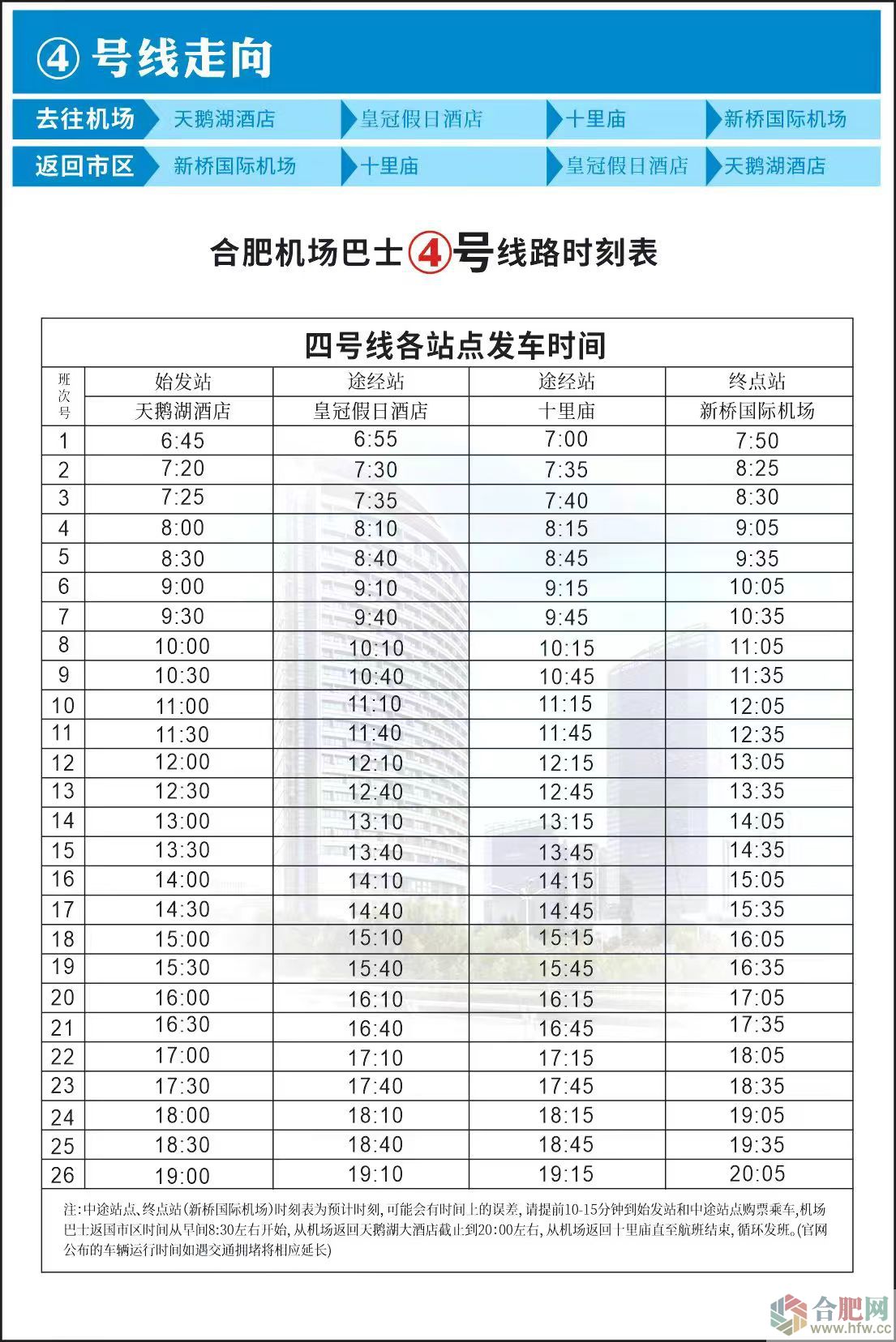
|
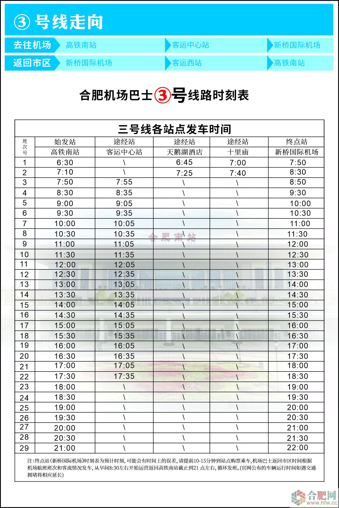
|
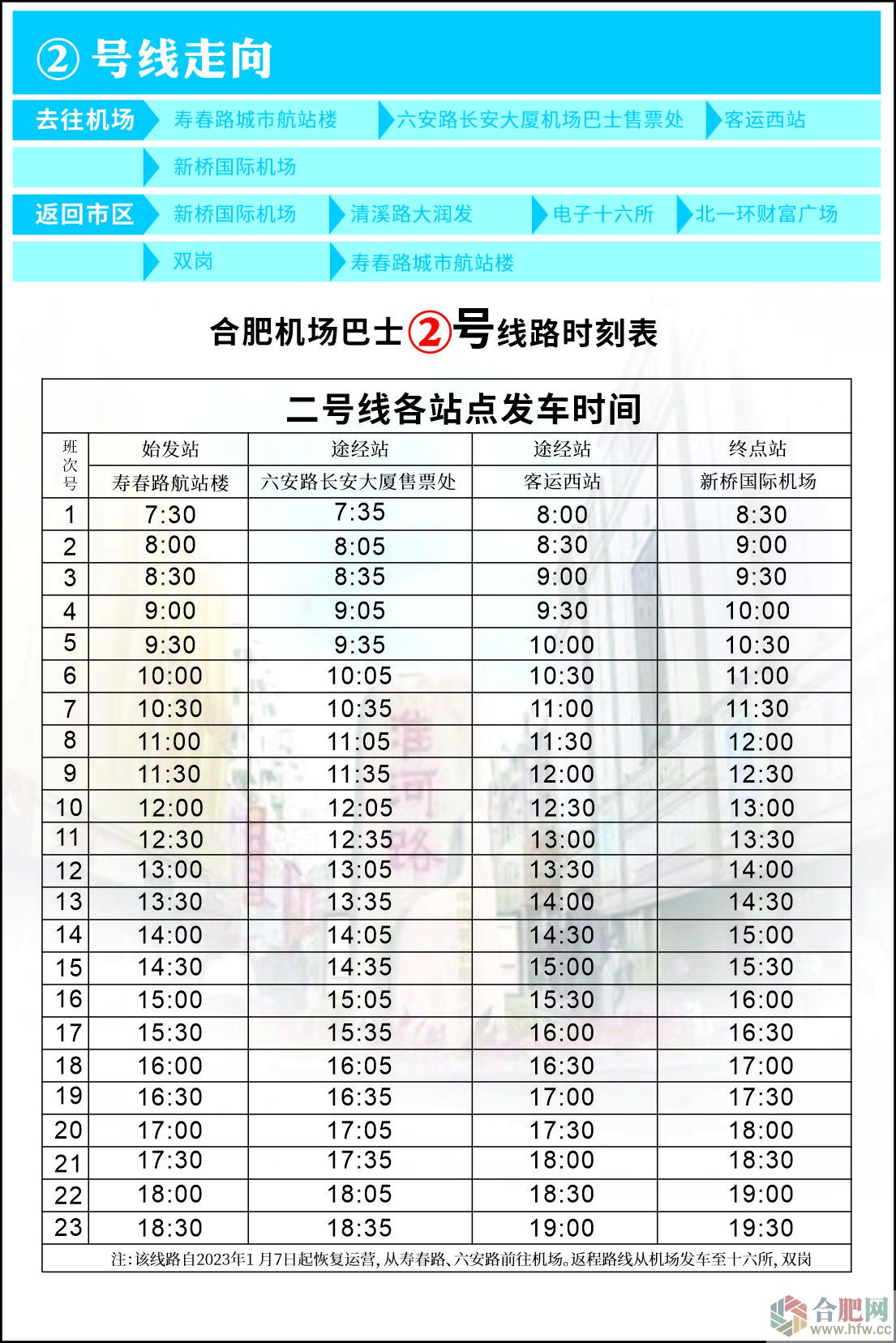
|
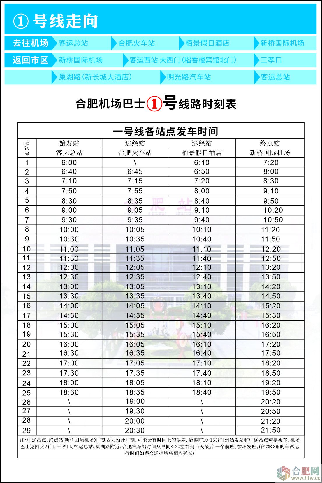
|
 |
¶جذإٍ×C´a ¾ئµêviشOس‹ NBAض±²¥ ژإ°²دآفd
Copyright © 2025 hfw.cc Inc. All Rights Reserved. ؛د·ت¾W °و™àثùسذ
ICP‚ن06013414ج–-3 ¹«°²‚ن 42010502001045